
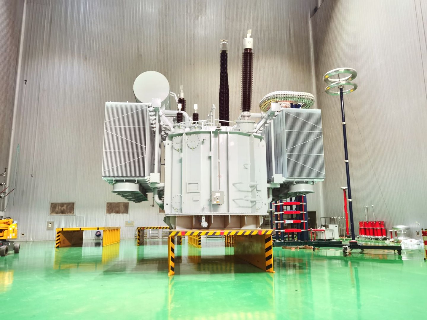
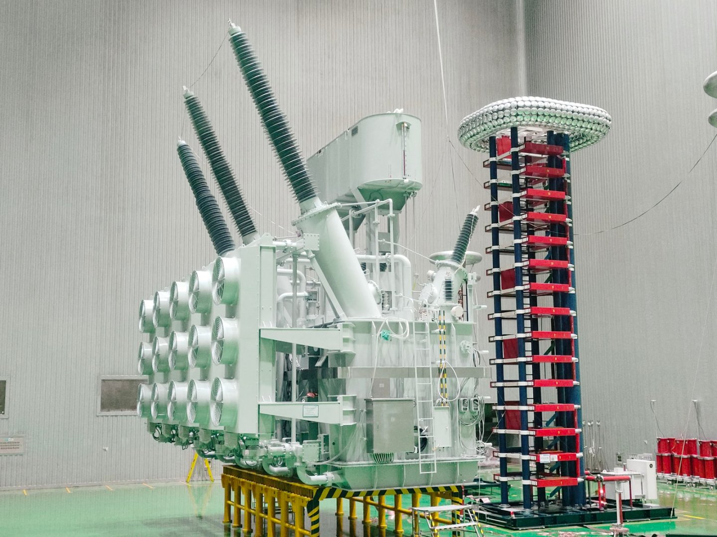
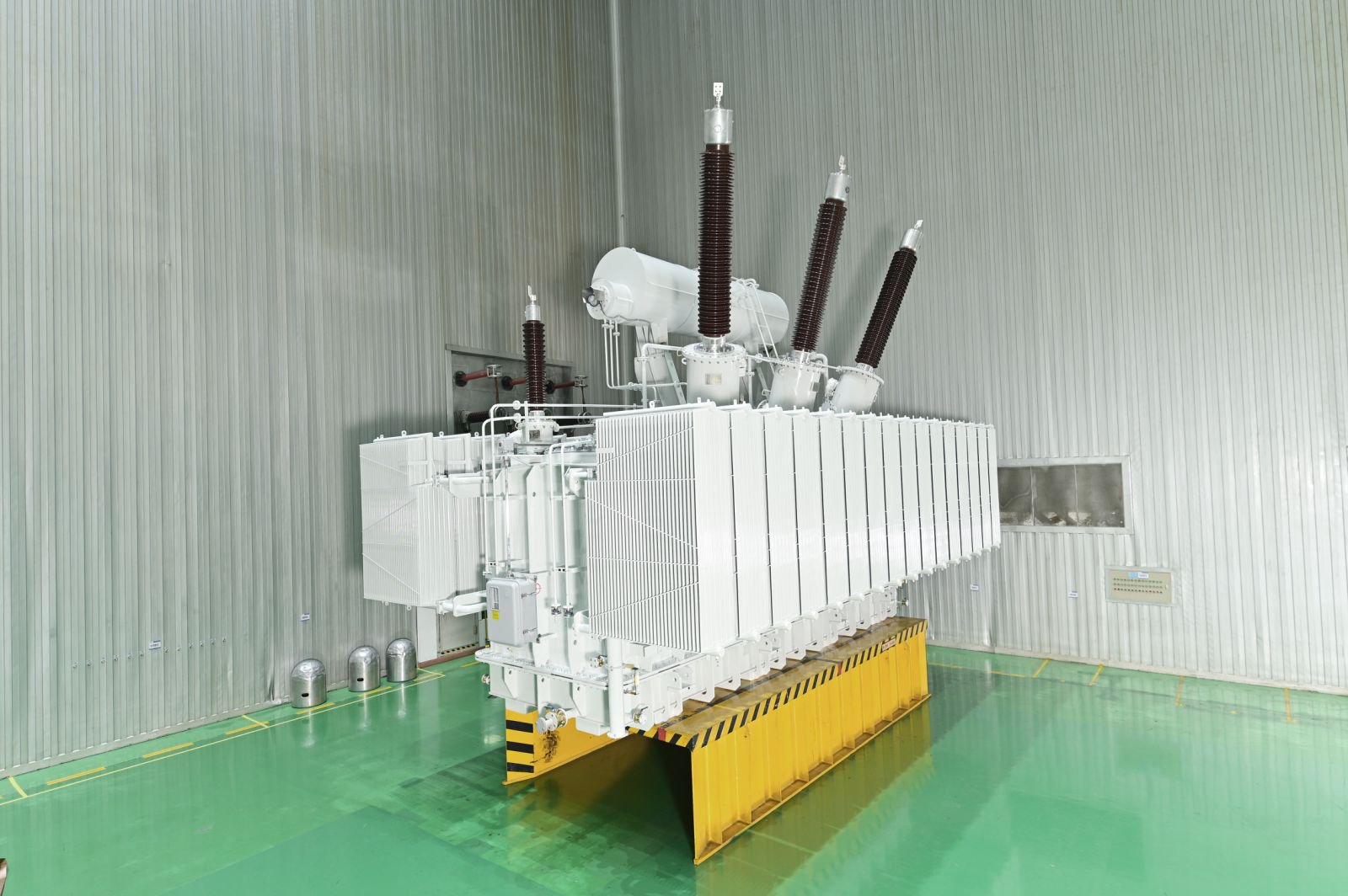
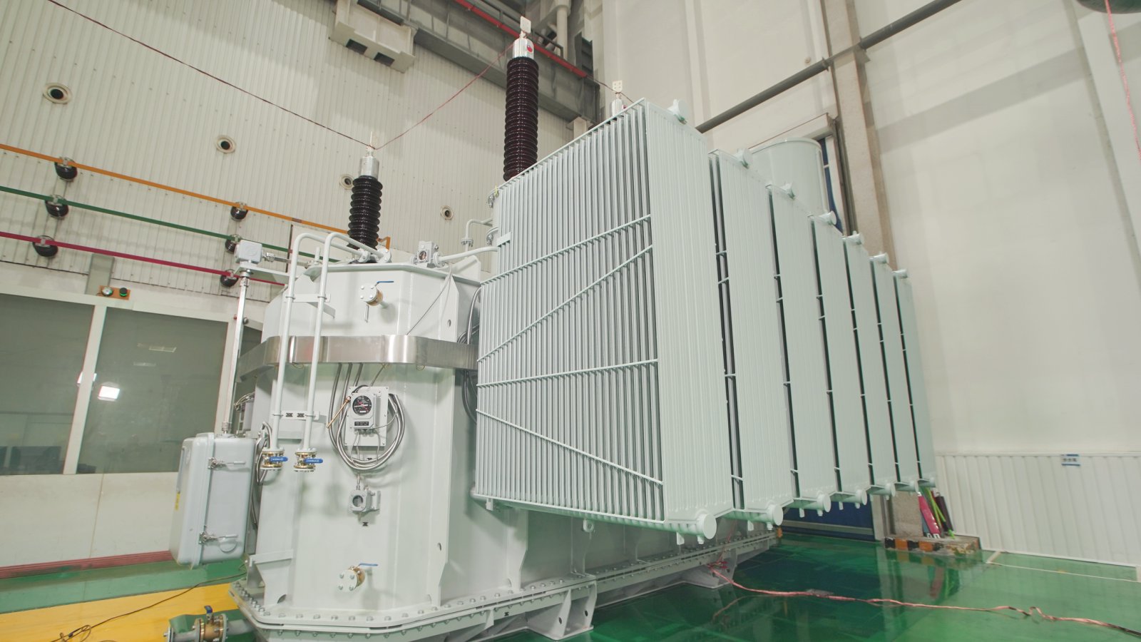
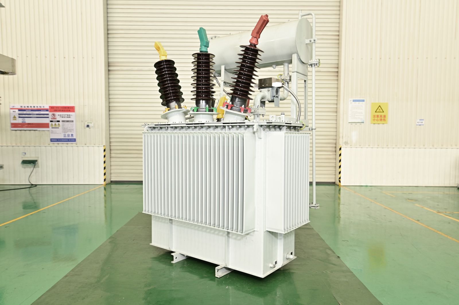

Selecting the correct three phase power transformer rating is essential for electrical system reliability, operating efficiency, and future capacity planning. An undersized transformer may experience excessive winding temperatures and accelerated insulation aging, while an oversized unit can increase equipment costs and no-load energy losses.
For industrial facilities and power substations, transformer capacity cannot be determined by connected load alone. Engineers must consider actual power demand, power factor, load diversity, motor starting characteristics, ambient temperature, cooling capability, and future expansion.
This guide explains how to calculate transformer kVA and MVA ratings, evaluate loading conditions, and prepare technical specifications for procurement.
Understanding Three Phase Power Transformer Ratings
A three phase power transformer transfers electrical power between three-phase circuits through electromagnetic induction. Its rated capacity is expressed in kilovolt-amperes (kVA) or megavolt-amperes (MVA), representing apparent power rather than active power.
The relationship between these quantities is:
Apparent Power (kVA) = Active Power (kW) / Power Factor
For example, an industrial facility requiring 4,000 kW at a power factor of 0.8 has an apparent power demand of:
4,000 / 0.8 = 5,000 kVA
Therefore, the electrical load requires 5 MVA of apparent power capacity before accounting for additional design considerations.
A transformer rated at 5 MVA is not automatically suitable for this project. Continuous loading, operating temperature, temporary overloads, and anticipated future demand must also be evaluated.
How to Calculate Three Phase Transformer Capacity
The basic three-phase apparent power formula is:
S (kVA) = √3 × V × I / 1,000
Where:
- S = Apparent power in kVA
- V = Line-to-line voltage in volts
- I = Line current in amperes
- √3 = Approximately 1.732
This formula applies to balanced three-phase loads.
Example 1: Calculating Transformer Capacity from Current
Consider a three-phase industrial distribution system with the following requirements:
| Parameter | Value |
|---|---|
| Line Voltage | 10,000 V |
| Maximum Load Current | 400 A |
| System Frequency | 50 Hz |
| Load Configuration | Balanced Three-Phase |
The apparent power demand is:
S = 1.732 × 10,000 × 400 / 1,000
S = 6,928 kVA, or approximately 6.93 MVA
A transformer with a continuous rating below 6.93 MVA would not be suitable for carrying this specified demand without an approved loading arrangement.
An 8 MVA transformer could meet the calculated demand under suitable rated operating conditions, but the final selection must consider anticipated growth, cooling limitations, and other project requirements.
Example 2: Calculating Transformer Rating from kW and Power Factor
Consider a manufacturing facility with:
- Maximum active power demand: 8,000 kW
- Power factor: 0.90
- Preliminary future load allowance: 15%
First, calculate apparent power:
8,000 / 0.90 = 8,889 kVA
Next, apply the planning allowance:
8,889 × 1.15 = 10,222 kVA
The preliminary design requirement is approximately 10.22 MVA.
For this example, a 12.5 MVA transformer would be a reasonable candidate for technical evaluation, subject to its available rating, cooling conditions, and the project’s electrical specifications.
The 15% allowance is an illustrative planning assumption, not a universal transformer sizing requirement. Actual capacity reserves should be based on documented expansion plans and engineering criteria.
Key Factors Affecting Three Phase Power Transformer Selection
1. Actual Load Demand and Diversity
Connected load represents the total rated capacity of installed electrical equipment. However, not all equipment necessarily operates at maximum demand simultaneously.
For transformer sizing, engineers should distinguish between:
- Connected Load: The total installed electrical load.
- Maximum Demand: The highest expected simultaneous operating load.
- Load Factor: Average load divided by peak load over a defined period.
- Diversity Factor: The sum of individual maximum demands divided by the maximum simultaneous system demand.
Transformer capacity should reflect the actual system demand and applicable engineering requirements rather than simply adding all equipment nameplate ratings.
For an existing facility, measured load profiles can provide a more reliable basis than estimated connected load.
2. Power Factor and Reactive Power
Power factor directly affects the apparent power that a transformer must supply for a given active power demand.
For an illustrative 5,000 kW load:
| Power Factor | Required Apparent Power |
|---|---|
| 1.00 | 5,000 kVA |
| 0.95 | 5,263 kVA |
| 0.90 | 5,556 kVA |
| 0.85 | 5,882 kVA |
| 0.80 | 6,250 kVA |
At a power factor of 0.80, the transformer carries 25% more apparent power than at unity power factor for the same 5,000 kW active load.
Power factor correction may reduce the apparent power demand seen by the transformer. However, capacitor banks and other correction equipment must be coordinated with system harmonics, switching conditions, and voltage regulation requirements.
3. Motor Starting and Temporary Loading
Industrial facilities containing large motors, compressors, pumps, or mining equipment may experience substantial starting currents.
Direct-on-line motor starting can produce current several times higher than the motor’s rated operating current. The resulting voltage drop depends on motor characteristics, transformer impedance, and the upstream network.
Engineers should evaluate:
- Motor starting current and duration.
- Permissible voltage drop during starting.
- Transformer short-circuit impedance.
- Frequency of motor starts.
- Available upstream short-circuit capacity.
- Use of soft starters or variable frequency drives.
Transformer selection should not be based on steady-state kVA alone when large motor starting is a significant operating condition.
4. Ambient Temperature and Cooling Capacity
Transformer thermal performance depends on the relationship between electrical loading, internal losses, ambient temperature, and the cooling system.
For oil-immersed three phase power transformers, common cooling arrangements include:
| Cooling Method | Operating Principle | Selection Consideration |
|---|---|---|
| ONAN | Oil Natural Air Natural | Natural cooling without pumps or fans |
| ONAF | Oil Natural Air Forced | Fans increase heat dissipation |
| OFAF | Oil Forced Air Forced | Oil pumps and air fans support forced cooling |
| ODAF | Oil Directed Air Forced | Directed oil circulation improves winding cooling |
Transformers with multiple cooling stages may have different rated capacities depending on which cooling equipment is operating.
The transformer datasheet should clearly state the rated MVA for each cooling stage.
IEC 60076-7 provides guidance on loading and thermal aging for mineral-oil-immersed transformers under different load and ambient temperature conditions.
5. Future Expansion and Capacity Reserve
Transformer projects often serve facilities expected to operate for decades. Future demand should therefore be considered during initial equipment selection.
However, selecting substantially more capacity than required is not always economical.
An oversized transformer can result in:
- Higher initial procurement costs.
- Greater space and transportation requirements.
- Potentially higher no-load losses.
- Lower operating load factors.
A practical sizing approach evaluates the expected load profile over the project’s planning horizon and balances future expansion requirements against capital and operating costs.
Three Phase Power Transformer Ratings for Different Applications
Transformer ratings depend on the electrical system, project scale, and operating requirements.
The following examples illustrate how sizing considerations differ by application.
| Application | Main Capacity Considerations |
|---|---|
| Industrial Manufacturing Plant | Maximum simultaneous demand, motor starting, expansion |
| Mining Facility | Heavy motor loads, load variation, site conditions |
| Utility Substation | Peak demand, network configuration, contingency loading |
| Solar Power Plant | Inverter output, generation profile, grid requirements |
| Wind Farm | Generation capacity, collection network, operating cycles |
| Energy Storage System | Bidirectional loading, converter characteristics, overload profile |
For high-voltage substations, transformer selection must also address insulation coordination, short-circuit withstand capability, and voltage regulation.
Liye Electric manufactures 110kV power transformers for utility substations, industrial power systems, and renewable energy projects. Transformer capacity and electrical configurations can be developed according to project requirements.
How Transformer Impedance Affects Rating Selection
Short-circuit impedance is another critical parameter when specifying a three phase power transformer.
It influences:
- Available fault current.
- Voltage drop under load.
- Protection system coordination.
- Load sharing between parallel transformers.
- Motor starting voltage performance.
For example, two transformers with identical MVA ratings but different impedance values may produce different fault currents and voltage regulation characteristics.
Transformer impedance should therefore be selected according to the electrical network design rather than treated as an independent product specification.
For parallel transformer operation, engineers must also verify voltage ratio, vector group, impedance compatibility, tap settings, and load-sharing requirements.
Transformer Losses and Operating Efficiency
Transformer losses affect long-term energy consumption and operating costs.
The two main loss categories are:
No-Load Losses: Primarily associated with the magnetic core and present whenever the transformer is energized.
Load Losses: Mainly associated with winding resistance and stray losses, varying with load current and operating temperature.
For a simplified operating loss estimate:
Total Loss ≈ No-Load Loss + (Load Factor)² × Rated Load Loss
Consider a transformer with:
- No-load loss: 20 kW
- Rated load loss: 100 kW
- Operating load factor: 0.60
Estimated losses at 60% loading:
20 + (0.60)² × 100 = 56 kW
This simplified example assumes consistent reference conditions and does not include auxiliary cooling power or other operating adjustments.
For projects with continuous operation, loss evaluation should consider expected annual load profiles rather than rated efficiency alone.
What to Include in a Three Phase Transformer Purchase Specification
Before requesting quotations, procurement and engineering teams should prepare a transformer technical specification.
| Specification Item | Information Required |
|---|---|
| Rated Capacity | Required kVA or MVA |
| Rated Voltage | Primary, secondary, and tertiary voltages if applicable |
| Frequency | 50 Hz or 60 Hz |
| Phase Configuration | Three-Phase |
| Vector Group | Required winding connection and phase displacement |
| Short-Circuit Impedance | Specified percentage and reference conditions |
| Tap Changer | OLTC or off-circuit tap changer; tapping range |
| Cooling Method | ONAN, ONAF, OFAF, ODAF, or other |
| Insulation Level | Power-frequency and impulse withstand requirements |
| Loss Requirements | Guaranteed no-load and load losses |
| Installation Conditions | Ambient temperature, altitude, site restrictions |
| Applicable Standards | IEC 60076, relevant IEEE standards, or project requirements |
| Testing | Routine, type, and special tests as specified |
For large substations, additional documentation may include a single-line diagram, load flow study, short-circuit study, transportation restrictions, and site layout drawings.
Clearly defining these requirements allows transformer manufacturers to prepare technically comparable proposals.
Three Phase Power Transformer Manufacturing at Liye Electric
Liye Electric provides custom transformer engineering and manufacturing services for industrial facilities, transmission networks, utility substations, and renewable energy infrastructure.
As a China transformer manufacturer, Liye Electric produces power transformers across multiple voltage classes, with manufacturing capabilities extending up to 750kV.
Our manufacturing processes cover core fabrication, winding production, insulation processing, oil tank manufacturing, assembly, and electrical testing.
For high-voltage projects, Liye Electric offers 220kV power transformers and 330kV power transformers, with electrical specifications reviewed according to the application.
Our engineering team can evaluate transformer rated capacity, voltage ratio, impedance, cooling configuration, insulation requirements, and applicable technical standards before production.
Frequently Asked Questions
How do I calculate the kVA rating of a three phase transformer?
For a balanced three-phase system, use:
kVA = √3 × Line Voltage (V) × Line Current (A) / 1,000
If the load is specified in kW, divide the active power by its power factor to obtain the apparent power requirement.
Should a three phase transformer operate at 100% rated capacity?
A transformer may operate at its rated capacity under specified rated conditions. However, actual loading must account for ambient temperature, cooling availability, load cycles, and applicable operating limits. A fixed loading percentage should not replace a project-specific thermal assessment.
What happens if a three phase transformer is undersized?
An undersized transformer may experience excessive winding temperatures, accelerated insulation aging, voltage regulation problems, and reduced operating reliability. The severity depends on overload magnitude, duration, ambient temperature, and cooling performance.
How much spare transformer capacity should be included?
There is no universal spare-capacity percentage suitable for every project. Reserve capacity should be based on future load forecasts, operational requirements, reliability targets, and economic evaluation.
Can two three phase power transformers operate in parallel?
Yes, provided their electrical characteristics and network arrangements are compatible. Engineers must verify voltage ratio, vector group, impedance, tap settings, and load-sharing conditions before parallel operation.
Conclusion
Choosing the correct three phase power transformer rating requires a comprehensive assessment of apparent power demand, power factor, load variation, thermal conditions, short-circuit impedance, and future expansion.
The initial kVA or MVA calculation establishes the required apparent power, but final transformer selection must also satisfy electrical performance, insulation, cooling, and operating requirements.
Liye Electric provides customized three phase power transformers for industrial facilities, power substations, and transmission and distribution projects.
Request a Three Phase Power Transformer Quotation
Send your required rated capacity, primary and secondary voltages, load profile, impedance, cooling method, applicable standards, and project location to sales@liyeelectric.com.
Our engineering team will review your specifications and discuss a suitable transformer configuration for your project.